FIA Technical Analysis Page
http://www.formula1.com/insight/technical_analysis/
Page with technical updates since Australia 2004 until now.
==============================================
Aerodynamics
Aerodynamics has become the most important part of racing during the latest years. It has nearly become the only way for engineers to gain considerable time on their opponents, considering the very strict regulations in todays motorsports.
F1 is thereby the one to keep an eye on, as it is the sport where the most money is spent on technical developments.
Though the engine power, the tyres and much more, the aerodynamic streamline is very important to make the cars that fast. Many problems should be faced before starting with the design of a car. Ensuring enough air gets to the car's radiators is critical, because it's important for the engine's power.
F1 configuration
F1 (and in general, all winged racing cars) can be considered to be canard configurations in the sense that the front and back wings are on opposite sides of the centre of gravity and both are "lifting" (strongly) in the same direction, in this case down.
The car should be considered in (at least) 3 parts; front wing, body and rear wing. Each of these parts should be optimised for downforce (i.e. "lifting" down) and low drag, with the accent very definitely on downforce. This downforce can be likened to a "virtual" increase in weight, pressing the car down onto the road and increasing the available frictional force between the car and the road, therefore enabling higher cornering speeds.
This allows today's formula-1-cars to withstand centrifugal forces from 4G as to where a passenger car with sport chassis begins to slip at 1G.
Drag
The following table shows C, the drag coefficient, of some particular geometric objects.

To calculate the aerodynamic drag force on an object, the following formula can be used:
F = ½ CDAV²
Where:
F - Aerodynamic drag force
C - Coefficient of drag
D - Density of air
A - Frontal area
V - Velocity of object
In this system, D as air density is expreseed in kg/m³. The frontal area is the surface of the object viewed from a point that object is going to. It's expressed in m³. The velocity should be placed in m/s, where 1m/s is 3,6km/h.
The overall effect on lap times can be calculated with this "Law of Amdahl".
S
eff= S
f/S
f(1-f)+f
Here 'f' is the fraction of the system (when this fraction generates 5% of the car's drag, then f is 0.05) that can be improved, S
f is the improvement factor on this fraction (division of the drag in Newtons and the new drag force after improving that element), and S
eff is the overall improvement that will be achieved.
Downforce
Aero foils in motorsports are often called wings, referring to aircraft wings. In fact they are very similar. F1 wings and winglets aim to generate high downforce, by having a high angle of attack, thus also increasing the drag of the aerofoil.
The evolution of an airfoil to what it is now is mainly thanks to our well-known friends Bernoulli and Newton, who initially had totally different views on generating downforce.
When a gas flows over an object (or when an object moves through a gas), the molecules of the gas are free to move around. They are not closely bound to one another as in a solid. Because the molecules move, there is a velocity (speed plus direction) associated with the gas. Within the gas, the velocity can have very different values at different places near the object. Bernoulli's equation relates the pressure on the object to the local velocity; so as the velocity changes around the object, the pressure changes as well, in the opposite way.

Now adding up the velocity variation around the object instead of the pressure variation also determines the aerodynamic force. The integrated velocity variation around the object produces a net turning of the gas flow.
From Newton's third law of motion, a turning action of the flow will result in a re-action (aerodynamic force) on the object.
So both "Bernoulli" and "Newton" are correct. Integrating the effects of either the pressure or the velocity determines the aerodynamic force on an object. These two equations have lead to the current airfoils used and make optimal use of both theories.
Design
Today's formula one cars are designed with CFD (computational fluid dynamics) and CAD (computer aided design) that allows engineers to design a car, and immediately simulate the airflow around it, incorporating environmental parameters like traction, wind speed and direction, and much more.
Further on, the richest teams can now test fully scaled cars in their closed circuit wind tunnels, which operate 24h a day.
__________________________________________________ ____________
Front wing aerodynamics
The front wing of a Formula One car creates about 25% of the total cars downforce. Although this only occurs in ideal circumstances. When a preceding car runs less than 20m in front, the total downforce generated by the front wing may become as little as 30% of its normal downforce. Although this reduce of drag (because the air pressure is lower behind a car's rear wing), enables higher speeds at the end of straight, it significantly hinders the pursuing car in corners, as he cannot take these at normal speeds. This problem mostly occurs in fast corners, and is one of the most important reasons of the overtaking problem currently in Formula One. It is therefore a hard job to create a performing front wing, even more because disturbing the airflow too much will affect the rest of the car's aerodynamic efficiency too.
Regulations:
3.4 Width ahead of the rear wheel centre line :
3.4.1 Bodywork width ahead of the rear wheel centre line must not exceed 1400mm.
3.4.2 In order to prevent tyre damage to other cars, the top and forward edges of the lateral extremities of any bodywork forward of the front wheels must be at least 10mm thick with a radius of at least 5mm.
3.7 Front bodywork height:
All bodywork situated forward of a point lying 330mm behind the front wheel centre line, and more than 250mm from the centre line of the car, must be no less than 100mm and no more than 300mm above the reference plane.
3.17.1 Bodywork may deflect no more than 5mm vertically when a 500N load is applied vertically to it 700mm forward of the front wheel centre line and 625mm from the car centre line. The load will be applied in a downward direction using a 50mm diameter ram and an adapter 300mm long and 150mm wide. Teams must supply the latter when such a test is deemed necessary.
Front wing design:
A regular front aerofoil is made as a main plane running the whole width of the car (almost at least, limited by FIA regulations) suspended from the nose. Onto this are fitted one or more flaps which are the adjustable parts of the wing. On each end of the mainplane there are endplates. These make sure the airflow passes above and beneath the wing rather than around it. In recent years these endplates have played a crucial role in influencing the airflow around the front tyres, especially after the rule changes at the beginning of 1998 (wheelbase made smaller from 220cm to 180cm). These changes made front wing airflow interfere with the rotating airflow around the front wheels.
Article 3.17 has been introduced during 1998, after teams started experimenting with bending front and rear wings. When Ferrari introduced such a front wing at the end of 1997, it was produced in such a way that the wing would flex under aerodynamic loads. This means that as the speed increased, a force was produced that pushed the wing towards the ground. By means of a ground effect, this was particularly interesting for front wings because if would increase downforce at high speeds without an increase of drag. As rear wings began to fail and flew off during races, the FIA thought it was time to act and added 3.17 to the technical regulations of Formula One.
At the beginning of 2001, front wing regulations had changed in such a way, that the wing should be 100mm above the ground at least, instead of the 40mm until then. The FIA introduced this change to limit the cornering speeds of the cars. The idea was to decrease the ground effect that was generated by front wings close to the ground, working just like a diffuser.
Immediatley at the start of the season, Ferrari introduced a front wing that was bent down in the center line or the car. This new concept makes a handy use of a little hole in the regulations. The whole is the result of a rule, added in 1994, where the wooden bottom made it's entry. This wooden plate can be hung up as low as possible to the ground. As this plate is 50 cm wide, it was not foreseen that the front wing may be placed that low to the ground in 25cm at each side of the center of the car. Since the introduction by Ferrari, more and more teams have adopted the idea of curved front wings, with them also McLaren and Renault (see picture).
Though the reason that McLaren didn't make any of those changes until 2002, might have to do with the curve of the front wing before the change of regulations. It was namely curved up in the middle, so that the inner side was higher above the ground then both outer sides of the front wing. This type of wing is mostly useful on fast tracks where not much downforce is needed. It is there that airflow in the centre of the car can be more used by the diffuser in the back instead of lifting it up and create downforce in the front.
End plates:

(Right Click, "view image" for a clearer view.)
Some of the air that is needed to generate the front wing's downforce interferes with the rotating air around the front wheels, F1 teams have been developing the end plates from a simple plate to an integral part of the wing. To overcome the main problem of turbulence around the wheel, McLaren, and later Ferrari made in 1998 the inside edges of the front wing endplates curved to direct the air between both front wheels. One year after, all teams had adopted this technique to maintain front wing efficiency. Some other teams decided to decrease the width of the main plane just to the width between the front wheels. This left some room for extra wings and flaps, which caused the beginning of intensive end plate research. In 1998 changes were so radical that Ferrari produced six different designs of front wings throughout 1999, in order to reclaim the lost downforce by regulation changes.
* Note that the regulations aren't up to date, since now front wings must have a higher ground clearance.
__________________________________________________ ____________
Nose Cone
High or low front wing
Designing
As the gap between Ferrari and McLAren is widening fast at the moment, there may rise some questions about the aerodynamics. The 2001 season is an example of a regulation chage that brings the need of a complete new aero packet. It is very remaquable that compared to 2000, McLaren raised their nose cone, and Ferrari drastically lowered it. Here's an explanation.
McLaren for example has raised the nose cone. All the changes to the F1 nose parts are due to the regulation change about the front wing, which is placed 5 cm higher above the ground. With it, there has been lost a lot of downforce on the front wheels. Although it ùmight seems very strange that McLaren raised the nose cone for this, but it makes a lot of sense. As most teams hieghtened up the nose cone, it is the most striking, also because Newey can be seen as a reference. The reason for it is the air flowing under the nose. Of course, the upper air flowing over the nose generates now less downfoce, but Newey certainly thought it wouldn't have a very high impact Benetton 2001 nose cone on itself.
So the air under the nose is pushed (over the front wing) or pulled (for air coming under the front wing) to higher levels. As the air has a lot more room under the nose in the center of the car, it can be more usefull then if it would be forced to change direction immediately. When the air can be directed to the sidepods smoothly, it causes a lot less resistance.

As shown on this Benetton picture, air flows up and is sort of pushed to the underside of the nose cone. Thanks to the high nose, the air can be "splitted" to both sidepods without very much air resistance. It is the same why Benetton did not place a very steep front wing part in the center, because they probably cannot handle the air going up under the cockpit between the front wheels. It wight be a big advantage of placing the front wing that low in the center, just because of this low air. This is probably the reason of opting for a high nose, exactly bacause of not losing the efficiency of the front wing.

Ferrari on the contrary have opted for a completed other tactic. They did not feel maintaining the front wing affeciency as a priority, although downforce on the front wheels is very important. So the most appropriate solution is the lower nose cone. Exactly what ferrari did, though with some changes. Thanks to the low nose top, much air that would not have any affect of the frontwing, is now flowing over the nose, with a lot of downforce as result. The underside of the nose, which seemed to be the most difficult problem with other teams, is solved with a curve. Passing the front wing, and going 30 cm further, the nose cone at that height could also be the one of a high nose. Once air has passed under the low nosetop, it can be pushed up by the front wing, without an obstacle. Once the airflow has passed this stadium, lots of downforsce has been generated, and the air is guided to the sidepods exactly the same way as with high nose cones. This might be the ingenious design of feerari, in which all other teams failed.
You have here immediately a reason for the extreme high level of downforce on the ferrari. The mechanics are able to increase the downforce on the rear wing, without getting the car stable, thanks to an efficient nose cone.
__________________________________________________ ____________
Rear wing efficiency
How it works
The basic principle of a formula one wing is exactly the same as with a common aircraft. The greatest difference is the direction air is pressed and how that aerodynamic force is generated. Knowing that an aircraft wing does the opposite of an F1 wing, I'll explain a formula one wing. I will start from the idea that we are testing a single rear wing in a wind tunnel. The main advantage of this theoretical example is that it leaves out some natural factors. With a single wing, we do not have to think about turbulence that is generated by the car itself (the engine cover mainly), neither do we have to take in account the direction and speed of outside wind. It is obvious that both these factors decrease the efficiency of a aerofoil.
As you can see in the picture below, air flows onto the rear wing with a straight direction (which is often called clean air) at the speed of the car. The white flaps push the air up. Following Newton's law, an action causes a reaction, which is why the aerofoil is being pushed towards the ground by the air. Having in mind that air flowing onto the flaps is pushed upwards, and underflowing air keeps going its own way, a low pressure area (nearing a vacuum at very high speeds) is created right behind the horizontal aerofoils. This 'vacuum' causes a suck up of the air passing under that flap. The underpassing air on the other hand again flows faster in an attempt to equalize pressure on both sides of the aeleron, and thereby increasing the total wing efficiency. Because of the car's speed this is impossible, which is why the effect is maintained. The force that is created by this type of wing, so that the car is pressed onto the ground, is called downforce.
 Rear wings
About a third of the car's total downforce can come from the rear wing assembly. The rear wings are the ones that are varied the most from track to track. As the rear wings of the car create the most drag the teams tailor the rear aerodynamic load to suit a particular track configuration.
As air flows over the wing, it is disturbed by the shape, causing a drag force. Although this force is usually less than the lift or downforce, it can seriously limit top speed and causes the engine to use more fuel to get the car through the air.
From the year 2001, the FIA regulations have changed concernig the rear wing. To increase the ability of overtaking and slipstreaming, the number of rear wing elements is now being limited to 3. This should decrease the downforce and acceleration. The only effect that might have come with this regulation change, is at high downforce circuits, there will be a little more air resistance to produce the same downforce.
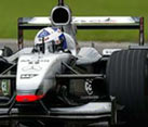
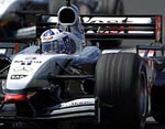
The pictures below both show David Coulthart in his MP4/17 from 2002. The picture of the left shows him at Monza 2002, whilst the picture on the right was taken at the Nurburgring. You can see that the rear wing profiles are very different. On the left picture, very little of the rear wing can be seen, whilst the Monaco wing has much of the profile visible:
 The diffuser

(Right Click, "view image" for a clearer view.)
The smallest thing which you can count to the wings part is the diffuser. Acually, it does exactly the opposite of a rear or front wings. Instead of pushing the air up, it sucks the air up. The volume of the diffuser increases towards to the end of the car.
Where a certain amount of molecules filled for example 1dm³ under the car, these now fill 2dm³. This drop of pressure causes a car to be sucked towards the ground. Driving at a speed of 300 km/h, the groundeffect of the car would be extreme if there was no air under the car itself. Therefore, the FIA has forbidden strokes and sloping car bottoms because of safety reasons. Instead of raising the back of the car, the diffuser sucks the air away from under the car because the low pressure. The diffuser us placed under the rear wing and is actually a sweep up of the car's floor. It consists of many tunnels and spliters which carefully control the airflow to maximize this suction effect. The design of the bottom of the car, and thereby the diffuser is a critical area, because it can greatly influence the car's behaviour in corners. More importantly, the designers have to be carefull that the car keeps working good in all circumstances, and at any distance from the ground. Losing all of the diffuser's generated downforce when riding over a curb will greatly generate a nervous behaviour of the car itself. The strokes and flips withing the diffuser have lately become that advanced (curbed and even foreseen by gurney flaps sometimes) that any track distance is insufficient to guarantee good performance. It is still a part where a lot of time can be gained on current F1 cars, partly by pulling more air towards the diffuser by inducing the coke-bottle effect.
- All credit goes to F1technical.
www.f1technical.net


 Linear Mode


